
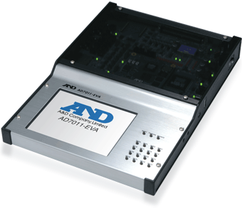
A Linux computer powered by an ARM11 core
– Optimized for MATLAB/Simulink target machines
– Comes with a software tool for easy creation of control console screen and graphical user interfaces (GUI)


AD7011-EVA Board

AD7011-EVA Board block chart

MATLAB/Simulink

Create control programs with MATLAB/Simulink
Create model-based control programs on a Windows PC using MATLAB/Simulink.
Required software: MATLAB2006b series, 2008b or 2009b series, MATLAB, Simulink, and Real-TIme Workshop. (Trial versions of MATLAB, Simulink and other software can downloaded from the Mathworks website.)
- MATLAB/Simulink R R
- Confirm the license information that is included with the software
- Supported Windoes operating systems
- Microsoft Windouws XP Professional SP3
- Microsoft Windouws Vista Vusiness SP1 (32bit)
- Microsoft Windouws 7 Professional (32bit)
* MATLAB and Simulink are registered trademarks of The Mathworks, Inc.
GUI design tool: AD-VirtualConsole Designer

- Easily design your own control console screnns on a host PC (Windows PC)
- Choose and place diversfied parts, such as indicators, switches, signals, and graphs, to create various console screens
- Console screens are created using drag and drop operations
- Personalize the color and size of screen parts
- After completing the screen, associate definitions with the control program, and then run the control program and console screen together
Bundled sofrware (A software DVD is bundled with AD7011-EVA)
- Host environment (Microsoft Windows)
- ARM cross compiler (cygwin + gcc4.1.1 + glibc2.4 + binutils2.17)
- ARM cross debugger (gdb 6.6)
- Application development environment (Eclipse 3.4.2 Ganymede Pleiades All in One + Code Generator Plugin for Eclipse)
- GUI development tool (AD-VirtualConsole)
- S-function for EVA board (DIO, UART, WatchDog, SPI, 1-Wire, I2C device, etc.)
- Host environment (Linux)
- ARM cross compiler (gcc4.1.1 + glibc2.4 + binutils2.17)
- ARM cross debugger (gdb 6.6)
- Root-file building tool (LTIB)
- Target environment (AD7011-EVA)
- Boot loader : RedBoot ·OS : Linux 2.6.19 + Real-time extension (Xenomai 2.3.4)
- Root file Diversified software (busybox, glibc, alsa, openssh, samba, etc.)
- Driver Library Driver Library for EVA (DIO, UART, WatchDog, SPI, 1-Wire, I2C device, etc.)
- Confirm the license information that is included with the software
- Supported Windows operating systems
- Microsoft Windows XP Professional SP3
- Microsoft Windows Vista Business SP1
AD7011-EVA Specifications
|
Model code |
AD7011-EVA |
|
OS |
Linux + Xenomai (Real-time extension) |
|
CPU |
Freescale i.MX31ARM1136JF-S (532MHz), I/D Cache: 16KB/ 16KB, L2 Cache: 128KB, floating-point coprocessor (VFP) |
|
Memory |
DDR SDRAM: 128MB, NOR: 16MB (for OS), microSD: 512MB (for applications) |
|
LCD |
LAT057A347F, 5.7-inch, TFT color, QVGA (320 x 240), 260,000 display colors, LED backlight, four-wire resistive touch display |
|
UART |
RS232C/RS485 (Switching)UART1 and UART2: D-sub 9-connector and pin header
UART3 to 5: pin header only |
|
USB |
Host: Type-A connector x 1OTG: Mini-AB connector x 1 |
|
Ethernet |
RJ45 connector x 1 |
|
SD |
SD card connector x 1 |
|
Sound |
Line in mini jack (Stereo) x 1, Line out mini jack (Stereo) x 1, Small speaker (Mono), Buzzer |
|
I2C |
MAX7325 Port Expander (8 push-pull, 8 open-drain output) × 2, pin-header output × 2 |
|
1-Wire |
DS18B20 temperature meter × 1, pin header × 1 |
|
Keypad |
4 × 4 matrix switch and pin header |
|
CSPI |
ADC: 4-ch, 12-bit, single ended, ±10V input, AD7323 (96 pin connector)DAC: 4-ch, 12-bit, single ended, ±5V output, AD5024 (96 pin connector) |
|
External bus |
ADC: 4-ch, 12-bit, single ended, ±10V input, AD7323 (96 pin connector)DAC: 4-ch, 12-bit, single ended. ±5V output, AD5024 (96 pin connector)
FPGA for control (LFXP2-5E-5QN208) |
|
Interrupt input |
LVTTL (96 pin connector) |
|
GPIO |
12-bit LVTTL (96 pin connector) |
|
Watchdog output |
LVTTL (96 pin connector) |
|
96 pin connector |
PCR-E96LMD+ male connector (mounted on board) [Honda Tsushin Kogyo Co., Ltd.] |
|
EEPROM |
93C66, 4k-bit x 1 (for storing base board information) |
|
JTAG |
CPU Module PLD pin-header for writing x 1CPU Module i.MX31 pin-header for debugging x 1 |
|
Board size |
210 mm / 8.27 inches x 297 mm / 11.69 inches (A4 paper size) |
|
Chassis size |
222 mm / 8.74 inches (W) x 317 mm / 12.48 inches (D) x 43 mm / 1.69 inches (H) |
|
Power source |
12V, 3.8A, AC power adapter (Standard), 3.0V button battery (for back-up) |
|
Usable temp range |
0 to 70°C |
|
Standard accessories |
Quick start guide, DVD (development environment software, manual, circuit diagram, etc.),AC adapter, PCR-E96FS+ (96-pin female solder type connector) [Honda Tsushin Kogyo Co., Ltd.] |
